PolyPhaser Combiner ProductsCS & PS SERIES
|
Employs UL497B listed gas tube
| Built-in sampler port with BNC connector
| Ideal for combined transmit/receive applications
| Multi-strike capability
| EMP rated protectors
| Sampler port is coupled to the antenna connector
| Flange mounting/grounding | Weatherize using two WK-ls (see page 54)
| Aluminum enclosure
| 18-8 stainless steel hardware | |
Mil Specs: Many - call with requirements.
TEN YEAR WARRANTY
SPECIFICATIONS:
Surge: 20kA IEC 1000-4-5 8/20µs waveform 138 JoulesTurn-on: 1200/dc Vt= 1800V
Turn-on Time: 7.Ons for 2kv ns
VSWR: </= 1 to 1 over frequency range
Insertion Loss: </=0. 1 dB over frequency range
Max. Power: 750W single channel
(see Appendix B for Multi=Channel Capability).
Temperature: -25oC to +50oC Storage Operating
Vibration: 1G up to 100Hz
ORDER INFORMATION:
IS-CS50HD Frequency Range: 800 to 900MHz,DIN 7/16 female connectors, flange mount
Throughput Energy (typical): 6.5nJ
IS-CS50HD-B Frequency Range: 800 to 900MHz,
DIN 7/16 female connectors, bulkhead mount
Throughput Energy (typical): 6.5nJ
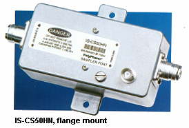
IS-CS50HN Frequency Range: 800 to 900MHz,
N female connectors, flange mount
Throughput Energy (typical): 6.5nJ
I5-CS50HN-B Frequency Range: 800 to 900MHz,
N female connectors, bulkhead mount
Throughput Energy (typical): 6.5nJ
IS-PS50HN Frequency Range: 890 ro 980MHz,
N female connectors, flange mount
Throughput Energy (typical): 6.5nJ
IS-PS50HN-B Frequency Range: 890 to 980MHz,
N female connectors, bulkhead mount
Throughput Energy (typical) 6.5nJ
IS-PS50HD Frequency Range: 890 to 900MHz,
DIN 7/16 female connectors, flange mount Throughput Energy (typical): 6.5nJ
IS-PS50HDB Frequency Range: 890 to 980MHz,
DIN 7/16 female connectors, bulkhead mount
Throughput Energy (typical): 6.5nJ
Add suffix: -MA for ma/e antenna port connector
-ME for male equipment port connector Energy based on 6kv/3kA 8/20µs waveform.

To speak to one of our consultants, please call us
at 1-800-543-8790