Appendix A - Part 1
Lightning Protection Information
GROUNDING OVERVIEW

The severity of a lightning strike is a statistically predictable event. an economically designed protection grounding (P/G) system should take into account a typical-to-large strike. The P/G system should be maintained on a monthly or at least
yearly basis. This should include testing protectors, measuring the ground system, pulling on ground rods, and protection grounding connections for corrosion and tightness. It should also involve a re-evaluation of the overall system design each time new equipment is installed,
moved, or modified.
A lightning strike starts with a local breakdown of the atmosphere (step leader) and steps about 150 feet in 1Ás time increments every 50Ás. During each of the 49Ás dormant stages, an imaginary hemisphere of 150' radius can be used to determine the next jumping distance. Any
object which penetrates this hemisphere, can be chosen as the point of attachment for the return stroke (lightning strike). Since this is a hemisphere, the geometry of a horizontal strike to a tower can occur anywhere above the 150' point over average terrain (side mounted
antennas above this height are vulnerable). This has led to the 150; radius rolling ball concept, where an imaginary ball is rolled along the ground in all directions. Each touch point of the ball with any ground mounted object is subject to an attachment point (hit). Coax
grounding kits should be installed 75' above the 150' point. Ins tall additional kits below 150' at the middle, bottom, and prior to the building entry bulkhead.
Lightning will take the path of least impedance which is both resistance and inductance. The larger the conductive surface, the lower the inductance. Bends add inductance - a coil is the continuous bending of a wire. Ground wires should be large and run straight for minimum
inductance and voltage drop. They also should be separated from all other conductors by 6" to 8" and should not be run inside or through a conductor unless they are bonded to it. In conduit, ground wires should be bonded at both the entrance and the exit. When working
with a metal wall, bond the ground wires to both sides. Do not go through the wall.

Your tower will be the point of impact like a pebble going into a still pond. The rings will be equipotential waves as they diffuse into the surrounding soil. The ground wires in the soil still have inductance. This inductance shunted by the soil
resistance, sets up a time constant or velocity of propagation (since capacitance is present also). The "ripples" will propagate faster with larger surface area wire and better conductive soil. The doping of soil with MgSO4 salts can help increase soil
conductivity and help retain water.
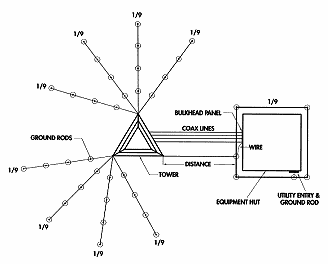
It is not necessary to run interconnecting rings around a tower. Self-support towers will equalize the surge current to each leg (the coax leg may have slightly more current). Guyed towers should not have rings, even if the rings are to act as a
collector for the radials. If each radial is interconnected directly to the tower base or leg, the inductance would be less than having only one or two connections going to a ground ring. Rings further out would be connecting radial ground rods that will have the same potential
at the same point in time, thus little current will flow as compared to taking the same material and effort and running another radial from the tower base.
 comm-omni@comm-omni.com
 Return to Comm-Omni Home Page
 Index
Index
To speak to one of our consultants, please call us
at 1-800-543-8790