Appendix A - Part 2
Lightning Protection Information

Guy anchors should be grounded with no dissimilar metals (see our book The 'Grounds' for Lightning and EMP Protection, Second Edition, Page 24). In poor soil conditions, radials can be used together with ground rods to ground the anchors.
A ground system can be obtained in many ways, but the most economical is with radials and ground rods. Radials of less than 100' will disperse the tower base or guy wire energy outward while the ground rods can help take it to lower, more conductive soil layers. If the surge is
not leaked or launched into the soil in the radial section(s), the ground rods, if lower soil conductivity can't be found, will develop high E fields and can arc in the soil to spread the charge outward. (This arcing is less likely in soils with higher conductivity.)
Arcing can cause glassification around the rod starting at the tip and working upward. The hot plasma fuses the silica sand into a glass which is a good insulator since water is boiled out in the process and can no longer re-penetrate the hardened glass. This is why, as a routine
maintenance, a tug on the rod which produces easy movement, is a possible indication of glassification.
The whole practice of lightning protection is to control the discharge path and not have it randomly disperse in any direction. In normally conductive soil, two rods should be spaced the sum of their lengths. One long deep rod or well casing will not be as effective as an array
of radials and ground rods. Even if the one deep rod measures a low resistance, the inductance is usually much greater. In conductive upper layer soil conditions, saturation can occur which cause eddy currents and additional inductance.
Unlike the radials, ground rod diameter size will have little effect on impedance unless the rod is very long. It is not always imperative to reach the water table, since this may be too far for the rod to be effective. It may be easier to salt dope the rod or use a chemical
ground rod that collects precipitation. In poor soil conditions, the spacing of ground rods should be closer. Poor ground conductivity will not shunt the radials' inductance, thus more ground rods will help by either reaching more conductive soil or arcing to relieve the voltage
potential. If not quickly dispersed, the voltage will build up at the tower and attempt to go another, perhaps unwanted, path.
All radials should be run away from the equipment building. The more radials there are, the more the current is divided. A perimeter ground system (ring) around the building will help form an equipotential plane. If this ring is approximately equal (in length) to each radial and
if eight radials are used, each will have 1/9 the total surge energy. This will leave only 1/9 the strike energy to the equipment building perimeter ground. The perimeter should only have one interconnection to the tower base and should be just below the coax cable runs. For
mountain tops, where no conductive soil exists and only radials can be used, wide copper strap, 1-1/2" to 3" wide, should be used to minimize inductance.
The re-bar in the concrete tower base should be used to augment the grounding system. Concrete is conductive because of retained moisture and alkalinity. Tower J bolts or anchor bolts embedded in a conductive concrete tower base will couple strike energy to the concrete. The
surface area interface between bolt and concrete will conduct high current levels during a strike. If the ground system is not adequate, the current density could be high enough to cause arcing at the bolt/concrete interface. When the re-bar is interconnected with the bolts,
there is additional surface area interface with the concrete, reducing current density. With more surface area and less current density, arcing in the concrete is less likely to occur. If the ground system is not adequate, the current density will be high enough to cause arcing
at the bolts. By interconnecting the re-bar, the current density will be reduced and arcing will be less likely to occur. To learn more on designing with the re-bar, consult the book The 'Grounds' for Lightning & EMP Protection, Second Edition.
It is not necessary to route a single copper ground wire up a large galvanized steel tower. The difference in resistance between copper and galvanized steel is lost when compared to the inductive voltage drop due to surface area (skin effect). Placing a lightning rod at the tower
top and using the copper cable and tying it to ground is ineffective. The inductive voltage drop of the wire (>100kV) will cause it to jump (arc) to the tower, unless it is at least 24" from the tower. In fact, the use of bare copper cable can cause a corrosion problem to
the tower and should not be used unless covered. Copper should never come in contact with galvanized steel. Tinned copper wire should not be used in ground together with copper ground rods since the tinning will be leached into the soil very quickly.
Increasing the distance between the tower and coax cable entry provides additional propagational time for the tower ground to absorb the strike energy. At the building entry bulkhead panel, coax protectors should be used in addition to another set of coax grounding kits. This
bulkhead panel should have ground connectors connecting it to the perimeter ground with the same circumferences as the combined circumferences of the coax cables. Tower lighting protectors should also be included and grounded at this same point.
In a P/G system design, one should also think of system noise reduction and EMI/RFI (Tempest) shielding. This can be accomplished with a single point grounding system. Sometimes the use of a single ground bus (called the Principal Ground Window or PGW) can act as your single
point. All your equipment chassis should be grounded to this bus. It should be a large surface area connection to the ground system such as a PolyPhaser Bulkhead Panel, PEEP or PEP.
Typically, the plasma column of the lightning strike (return stroke) can have a voltage rise time of 20-50 nanoseconds. If it hits a tower, the tower will handle the majority of the current pulse to ground. The tower will also radiate the RF energy of the strike. The near field
(high magnetic or H field) will penetrate equipment interconnecting wires and induce surge energy. A Faraday cage can reduce this energy. A halo ground system with multiple down conductors to the outside perimeter ground loop can act as a quasi-Faraday cage and give some low
frequency shielding. Properly bonded metal building panels can act as a more effective cage. Double-walled screen rooms offer the greatest isolation.
Tower flasher lines, both strobe and conventional should have protectors to prevent surge entry into the building on the power lines as well as nuisance damage to strobe PC boards.
To ensure survival of the building equipment, all Inputs/Outputs (I/Os) must have protection and they should all be ideally located at the principal ground window or bulkhead panel. If these I/Os (power, telco, etc.) enter elsewhere, protect them
first at the entry point (ground protector to perimeter) next run to Perimeter ground Window (PGW) then protect it again before distribution by the cable trays. (Note: All trays should be grounded to the PGW or bulkhead panel.)
TYPES OF PROTECTORS
The best type of protector is an in-line type. It can better clamp and protect, while preventing the sharing of surge voltage and current with equipment. For telco lines, the best protector is needed when just a few lines are used. Every ground
system will momentarily saturate or elevate with respect to the surrounding area until the surge can propagate and dissipate into the soil. The evaluated site ground system can force "on" protectors (power and telco) and dump surge energy onto outbound lines. The
greater the number of telco lines, the more the surge is divided as it is distributed over these pairs. The single pair needs the world's best protector to ensure equipment survivability from overvoltage stress as larger surge energy is diverted to this single outbound pair.
LOCAL AREA NETWORKS
When coax or twisted pairs are used in LAN or WAN systems, a problem between different local grounds can occur. This can cause protectors, which protect in differential mode (wire to wire) as well as in common mode (wire to ground) to see a
voltage over the turn-on threshold between wires and grounds and clip, induce a hum, or not allow the system to operate. This is not the fault of the protector, but the system design. Grounds should be in common, or on an isolated ground adapter.
POWER LINE
Lightning and surge protectors are no substitute for an Uninterruptable Power Supply (UPS). However, many UPS units do not have adequate surge protection. In-line protectors can offer filtering of the line; however, many protectors use ferrite
core material which will saturate on major surges and be useless. Air core type indicators may not offer as low a cut off frequency or as much filter attenuation and are physically larger, but they will not change with surge current or become less effective due to ferrite core
magnetic orientation. (PolyPhaser uses only air core inductors.) If your equipment is sensitive and critical, it should be on a UPS, which will buffer any line noise from your system since the ac power is regenerated. (Filters do not absorb or dissipate energy, but merely shunt
or reflect it back to its source.)
Power line protectors that cover the wall outlet when they plug in are only good for stand-alone equipment with no other I/Os. This is because other I/Os can input a surge to the equipment. A power line protector, which is far away on the end of a an inductive cord, will not
limit the overvoltage due to the inductance of the cord's safety ground wire. Protectors should be in common with (by a short interconnection) the chassis of the equipment that is to be protected and not at the end of a long equipment power cord. This may be hard or impossible to
do with consumer type protectors in plastic enclosures, but not with PolyPhaser's conductive aluminum case.
Semiconductors, whether silicon based or Metal Oxide Varistors (MOV), will fail in a shorted mode when they are at the end of life, or when over powered beyond their designed capabilities. However, if subjected to power levels in excess of the fusing levels of the
wire leads, the unit may fuse open.
Gas tubes normally fail in a shorted mode. Once shorted, another large strike can explode the gas tube creating an open circuit. Lab test levels show that our IS-NEMP, IS-B50 and IS-50 series models will vent the gas tubes at 899kA and above using the IEEE 8/20µs waveform.
This is just an overview of proper grounding and protector installation. For a more in-depth study, the 100+ page book The 'Grounds' for Lightning and EMP Protection will provide additional information and is available for order.
TESTING AND CUSTOM PRODUCTS
Testing can be done on any product. Please indicate the type of testing that you need. Testing results to Mil specs such as MIL-STD-462 or equal can be obtained in writing only. Some results may be considered proprietary and may not be released.
Custom products designed for customers, can at our discretion, be sold to others (including foreign governments) unless we are notified in writing.
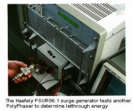
SURGE LET-THROUGH ENERGY TESTING
The let-through energy for PolyPhaser products is determined by testing the products with a Haefely PSURG6.1 surge generator equipped with a Hybrid Network input module, which will output a surge waveform compatible with IEC 1000-4-5 requirements
for coaxial products. The surge generator is capable of a 6kV by 3kA combined waveform.
Products are connected to the surge generator through antenna or surge side connector of the device under test (DUT). The surge let-through energy is measured by capturing the voltage waveform on the equipment or protected side of the DUT with an H.P. 54522C oscilloscope through
a length of line which has the specific impedance compatible with the DUT (50 ohm coaxial line, twisted pair line, etc.).
The digitized captured waveform is then mathematically processed to determine the let-through energy.
Our largest surge generator can produce up to 100kV and 65kA 8/20µs waveform IEC 1000-4-5.
 comm-omni@comm-omni.com
 Return to Comm-Omni Home Page
Index
To speak to one of our consultants, please call us
at 1-800-543-8790